Logic Probe 16
16-channel logic analyzer probe for Rigol MSO5000 series oscilloscopes. Based on the open-source S. Petrukhin design. Assembled, tested, and enclosed by SAM Controllers.
What This Is
The Logic Probe 16 v2.2 converts 16 single-ended digital signals into LVDS pairs that your Rigol MSO5000 can read through its 50-pin logic analyzer port. It is powered entirely by the scope. There is nothing to configure — plug it in, connect your signals, and the scope sees 16 digital channels.
Signal Path (per channel)
The SN65LVDS1 has a fixed switching threshold of approximately 1.4V (at 3.3V supply). Signals above ~1.4V read as logic high; below as logic low. Per TI datasheet, the input accepts voltages up to 5V regardless of supply voltage.
How It Works
Connect to Scope
Plug a 50-pin IDC ribbon cable from the probe’s P3 connector into your MSO5000’s logic analyzer port. The probe draws power from the scope’s +4V rail. The on-board LED confirms power.
Attach Probe Wires
Connect jumper wires or grabber clips from P1 (D0–D7) and P2 (D8–D15) to your circuit. Connect a ground wire between the probe and your circuit — LVDS requires a common ground reference.
Capture & Decode
Press Logic Analyzer on the scope. All 16 channels appear as D0–D15. Add protocol decoders (SPI, I2C, UART, parallel bus) and trigger on any digital channel.
Specifications
Logic Probe 16 v2.2
Rigol PLA2216 retails for $399 at Saelig
- Channels16 (D0–D15), single-ended
- Input connectorsP1 (D0–D7) + P2 (D8–D15), 2×8 pin headers, 2.54mm pitch
- Input voltage0–5V (per TI SN65LVDS1 datasheet)
- Switching threshold~1.4V fixed (TTL-level, not adjustable by scope)
- Driver ICTI SN65LVDS1 ×16, SOT-23-5
- LVDS termination100Ω per channel (R100–R115)
- Input protectionSeries resistors R0–R15
- Voltage regulatorON Semi MC33375ST-3.3T3G, SOT-223 (260mV typical dropout)
- Power source+4V from scope via 50-pin connector
- Scope connectorP3, 50-pin IDC header, 2.54mm pitch
- PCB2-layer, approximately 60×80mm
- Mounting4× M3 holes
- IndicatorPower LED
- Enclosure3D-printed case
- Passives0805 throughout
- Design originS. Petrukhin, open source (EasyEDA), Oct 2020
What It Does Well
3.3V and 5V Logic
The ~1.4V threshold sits comfortably between the noise floor and the logic-high level of 3.3V and 5V circuits. Arduino, ESP32, STM32, Raspberry Pi GPIO, PIC, AVR, classic 74HC/74HCT — all produce clean captures.
Protocol Decoding
The scope’s built-in decoders work on the digital channels: SPI, I2C, UART, RS-232 (with transceiver), and parallel bus. You can trigger on protocol events and correlate digital captures with analog channels on the same timebase.
Documented & Repairable
Every component is identified: 16× TI SN65LVDS1 (SOT-23-5), MC33375 LDO (SOT-223), 100Ω termination resistors, 0805 passives. Full open-source schematic. If a channel fails, you can isolate and replace a single driver IC.
Proper LVDS Termination
Each channel has a 100Ω parallel termination resistor. The MSO5000 provides 33Ω series resistance internally but does not terminate the LVDS pairs. Without the on-probe 100Ω termination, you get signal reflections and unreliable captures.
What It Does Not Do
Comparison — Every Option on the Market
There are four distinct approaches to getting a 16-channel logic probe for the MSO5000. Each uses different ICs and has different trade-offs.
| Specification | Rigol PLA2216 | eBay Clones (v3) | Climbers.net v3.1 (DIY) | Logic Probe 16 v2.2 |
|---|---|---|---|---|
| Price | $399 | $80–$96 | ~$15 (DIY BOM) | $30–$195 |
| Sold as | Assembled | Assembled | DIY only (KiCad files) | PCB, assembled, or kit |
| Signal IC | LMH7322 dual comparator (×8) | SN65LVDS391 quad driver (×4) | SN65LVDS391 quad driver (×4) | SN65LVDS1 single driver (×16) |
| IC type | Comparator (adjustable ref) | LVDS driver (fixed threshold) | LVDS driver (fixed threshold) | LVDS driver (fixed threshold) |
| Threshold | Adjustable via scope UI | Fixed ~1.4V TTL | Fixed ~1.4V TTL | Fixed ~1.4V TTL |
| Max input | ±40V | 5V | 5V | 5V |
| Termination | 100Ω | 100Ω | 100Ω | 100Ω per channel |
| LDO regulator | Custom | Unknown | TLV743P | MC33375ST-3.3T3G |
| PCB | 4-layer | 2-layer | 2-layer, 80×60mm | 2-layer, ~60×80mm |
| Input protection | Yes | Unknown | Basic | Series resistors (R0–R15) |
| Power LED | ✕ | Unknown | ✕ | ✓ |
| Schematic | Proprietary | Not provided | ✓ Open source (KiCad) | ✓ Open source (EasyEDA + KiCad) |
| Enclosure | Injection molded | Varies (some with tray) | None | 3D-printed case |
| Accessories | Cable + clips + leads | Cable + clips | None | Kit option: cable + clips |
| Ships from | Distributor | China (2–4 wk) | Self-build | USA (2–3 days) |
| Design origin | Rigol (proprietary) | Based on Peter Lampe v3 | Peter Lampe v3.1 | S. Petrukhin v2.2 |
Scope Compatibility
MSO5072 / MSO5074
Confirmed compatible
MSO5102 / MSO5104
Confirmed compatible
MSO5204 / MSO5354
Confirmed compatible
DHO914 / DHO924
Same 50-pin connector. Community reports suggest compatibility but we have not tested it. Ask us before ordering.
MSO1000Z series
Not compatible.
Uses a different probe (RPL1116) with a different pinout.
Other scopes
This probe only works with scopes that have a 50-pin MSO5000-style logic analyzer port.
What’s Included
Bare PCB — $30
Unpopulated 2-layer board. BOM with part numbers for LCSC / Mouser / DigiKey. Links to EasyEDA and KiCad schematics. All passives are 0805. SN65LVDS1 is SOT-23-5.
Assembled — $155
Fully soldered board. Every channel tested for correct LVDS output before shipping. No enclosure or accessories.
With Enclosure — $175
Assembled and tested board in a 3D-printed case with M3 standoffs. Cutouts for P1, P2, and P3 connectors.
Complete Kit — $195
Enclosed probe + 50-pin IDC ribbon cable + 16 mini grabber clips for connecting to your circuit.
Design Details
About This Design
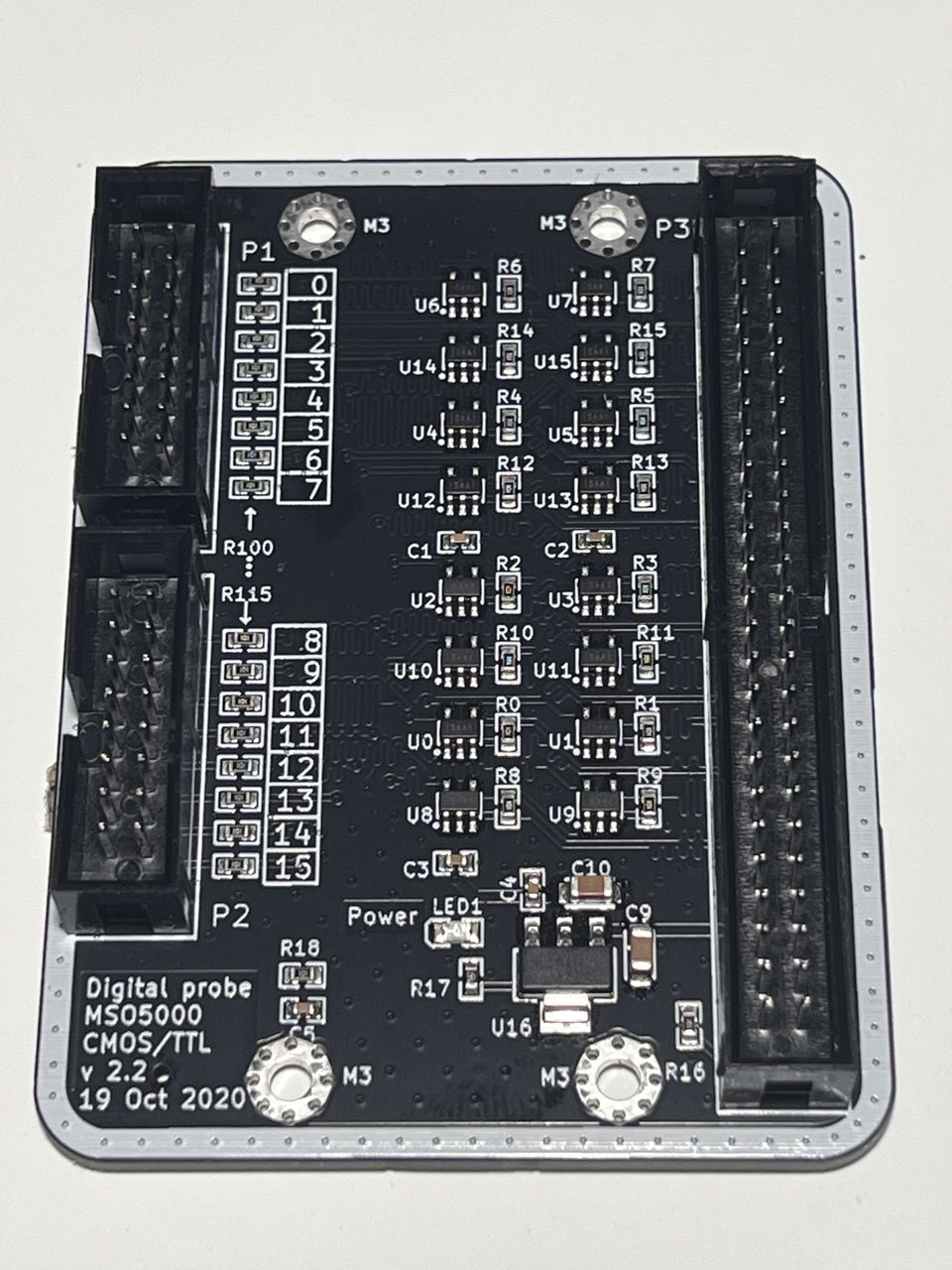
The Logic Probe 16 v2.2 is based on the open-source “Digital probe MSO5000 CMOS/TTL v2.2” by S. Petrukhin (EasyEDA/OSHWLab project), published October 2020. The design also has a community thread on EEVblog with discussion of the design decisions, alternative approaches, and user build reports. A KiCad conversion with improved trace routing is also available from hydrabus.
Component Details
U0–U15: 16× TI SN65LVDS1 single LVDS drivers
U16: ON Semi MC33375ST-3.3T3G LDO (4V→3.3V, 260mV dropout, 300mA)
R0–R15: Series input resistors (protection)
R100–R115: 100Ω LVDS termination
R16: Probe detect pull-down (scope sees the probe is connected)
R17: LED current limiter
C1–C5, C9, C10: Bypass/decoupling capacitors
P1, P2: 2×8 pin input headers
P3: 50-pin IDC connector
Frequently Asked Questions
Does the scope’s threshold setting affect this probe?
No. The MSO5000 sends a reference voltage on pins 36–37 of the 50-pin connector for probes that use comparators (like the Rigol PLA2216). This probe uses SN65LVDS1 drivers which have a fixed TTL-level threshold (~1.4V) and do not read the scope’s reference voltage. Changing the threshold in the Logic Analyzer menu will have no effect.
Will this work with 1.8V logic?
Unreliably. A 1.8V logic-high signal is only 0.4V above the ~1.4V threshold, which leaves very little noise margin. You may get captures that work on a clean bench but fail with any noise. For 1.8V logic, you need a probe with an adjustable threshold, such as the Rigol PLA2216.
Can I decode CAN bus or RS-485?
Not directly. CAN and RS-485 are differential buses. This probe has single-ended inputs. You would need an external transceiver IC (e.g., MCP2551 for CAN, MAX485 for RS-485) to convert the differential signal to single-ended, then connect the transceiver output to the probe.
Is this probe identical to the Rigol PLA2216?
No. Different ICs, different circuit topology, different PCB design. The PLA2216 uses LMH7322 comparators (~$8–12 each, 8 ICs), adjustable threshold, ±40V input range, on a 4-layer PCB. This probe uses SN65LVDS1 drivers (~$0.50 each, 16 ICs), fixed threshold, 0–5V input, on a 2-layer PCB. For 3.3V/5V signals they produce the same result on your scope screen.
Why not just buy the cheap one on eBay?
The $92–$96 eBay probes work for many people. The difference: their ICs are not documented (no datasheet, no schematic), termination is unverified, support is nonexistent, and shipping takes 2–4 weeks from China. This probe uses documented TI parts with a published open-source schematic, ships from the US in a few days, and you can email us if something doesn’t work.
How is this different from a Saleae or other USB logic analyzer?
USB logic analyzers stream data to a PC. This probe connects to your oscilloscope’s built-in logic analyzer — you see analog and digital channels on the same timebase, with the same trigger system, on one screen. If you already have a Rigol MSO5000, this unlocks the 16-channel logic analyzer hardware that’s already built into the scope.
What does the bare PCB include?
The unpopulated board, a BOM listing all component values with part numbers for LCSC/Mouser/DigiKey, and links to the full schematic in EasyEDA and KiCad formats. All resistors and capacitors are 0805 (solderable with a standard iron and flux). The SN65LVDS1 in SOT-23-5 requires a fine tip or hot air.
Does it need external power?
No. The probe draws power from the +4V rail that the MSO5000 provides through the 50-pin connector. The on-board MC33375 LDO regulates this down to 3.3V. When the LED lights up, the probe is powered and ready.