0
  • No products in the cart.

PWM DC Pedal Controller

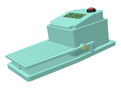
PWM DC Motor Pedal Controller provides reliable and repeatable control for any DC load to up to 35A.  

A basic version with simple multicolor LED will inform you on general status of the controller, and Buzzer will provide additional audible confirmation on process starts and alarms.

With optional 4 digit, 7 segment display could be build any type of winding or conveying mechanism, where need to count events, and input could be from any dry relay or NPN transistor.


As an advanced display option, we offer build-in 16 char x2 lines display with wide selection of information screen to show usage and performance parameters.


As a next step to upgrade, a remote 20 char x 4 lines display would be offered.

COMPONENTS

Controller

PWM DC Motor Pedal Controller are designed, manufactured, and tested to withstand industrial environment demand for stability and repeatability. All components have been selected to endure heavy salty mist environment. With proper installation, wiring and connection, the design is comparable to an industrial IP27 environment.


Features:

  • Predictable and Repeatable control function of the DC load from the Foot Pedal interface with other features.
  • Multicolor LED provides a status conditions and with advanced option LCD screen provides wide variety of informatics.
  • Multiple options for Inputs and Outputs create an endless usage scenarios.

INSTALLATION

Preparation

First – make your plan of the installation. Drawing a one line diagram would be a good start, but eventually you need to add details to your plan and make clear which individual wire is going in what position. If you have reservations about self-installation, consult a knowledgeable friend or contact us and we can assist in clarifying.


Tools and materials required

Plan and order required wiring to do your project. Add connectors, wire holders, etc. as needed.


Wire routing and connection

With your wiring diagram completed and ready, clearly think through how each wire will be routed and connected to the Controller. Make installation diagram if it will be helpful. It is advisable to use plastic clips, wire in corners using a wire guard, etc.


Optional connections

Optional connection need to be brought to site vision, as an important element of the installation needs.  Be sure to review the current ratings and use any additional equipment as you need to assure safety and installation longevity.

USAGE

Default Power ON

The PWM DC Motor Pedal Controller will do an autonomous self check upon powering on Pedal press status and all connected sensors, check the loads status, which takes less than 5 sec. After the check is completed, the software will monitor Pedal activation and generate PWM rated to specified Amps.


Advanced through screen

If advanced options for LCD display is selected, the Controller screen advancement will go from default screen to other informatic screens and status windows. Please consult a product User Guide for details.

SPECIFICATIONS

Standard Options
Input Power 12V DC to up to 50V DC Compatible power supply from 120V AC, plug in to wall, brick
Consumption Up to 0.1A without load current At power backup from battery consumption drop to 700mA
Display Multicolor status LED

  • Green – Power Ok
  • Blue – working
  • Red – malfunction
1) 4 digit 7 segment counter display, to reflect %% of power or Counter, color Red, Green, Blue, Yellow.

2) LCD, 3” x 1”, 16 chars x 2 lines, color Blue, Green, Yellow, White, Red

Foot Pedal Power Control Aluminium Industrial design, with 3 holes to attach to the floor, 0.5in working motion to control 0..100% output power.

Full protection – activation of whole functionality by follow the messages on screen – control by inside DIP switch, (required at least optional 16 char x 2 lines LCD display).

1) Maximum speed Trim

2) Minimum speed trim

3) “Cruise” control option to support “PushPedal-Keep-Forgot” to give a flexible operational environment. Look in to manual for details of operation.

4) Control by Digital Level input – reverse or direct selected by internal DIP switch.

Inputs Control from build in sensor from pedal motion to control output power
  1. Dual pedal with custom control functionality
  2. Counter
  3. Emergency Stop
Outputs (controllable) A single up to 35A DC output to control motors, lights, fan, industrial and scientific equipment 1) A dual 35A DC output with would be programm to do normal or reverse output function – user selectable inside DIP switch.

2) or First output Pedal output, and second control electric brake to up to 35A from remote or build-in trim pot.

Alarming Internal Buzzer could be activated on start operation – user selectable via internal DIP switch Alarm trigger output (dry contact)
Electronics Selectively coated to sustain ambient humidity
Enclosure construction Powder coated aluminium, corrosion resistant, IP27 protection Panel mounting hardware provided. Upgrade to 304 Grade  hardware.
Dimensions (W x H x D) 7.6” x 3.8” x 2.9”  

(192mm x 98mm x  75mm)

Construction temperature range Survive : -40F to +257F

             (-40C to +125C)

Powered :  -4F to +248F

              (-25C to +120C)

Request more information


    Send us a message.