0
  • No products in the cart.

Water Well Pump Controllers

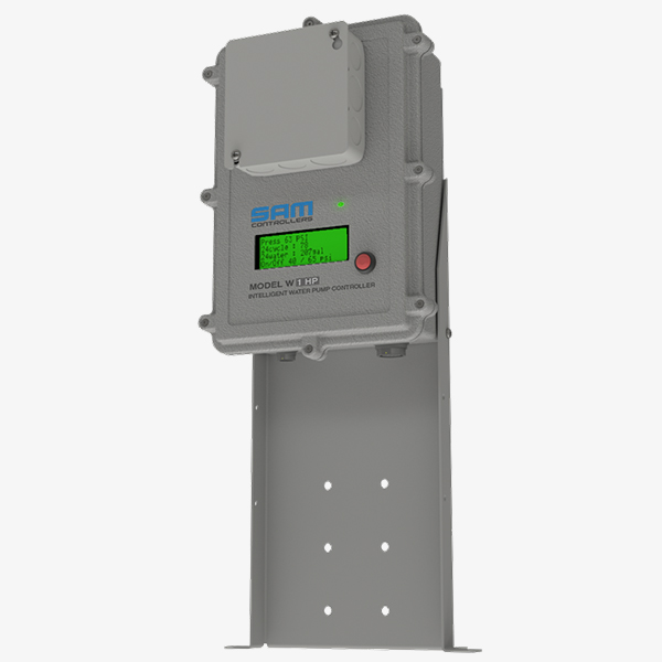
The physics behind water well pumps is universal and the SAM Controller provides control, data and analytics for all of them. No matter the pump application, the SAM Pump Controller will improve the performance, reduce the operating costs, extend the life of the water and sewage pumps.


The SAM Well Pump Controller is flexible with multiple inputs and outputs to satisfy almost any configuration with highly valuable applications.


Know when your water well pump is going to fail beforehand to save money and prevent a sudden disaster.


Feature Highlights of the SAM Pump Controller 

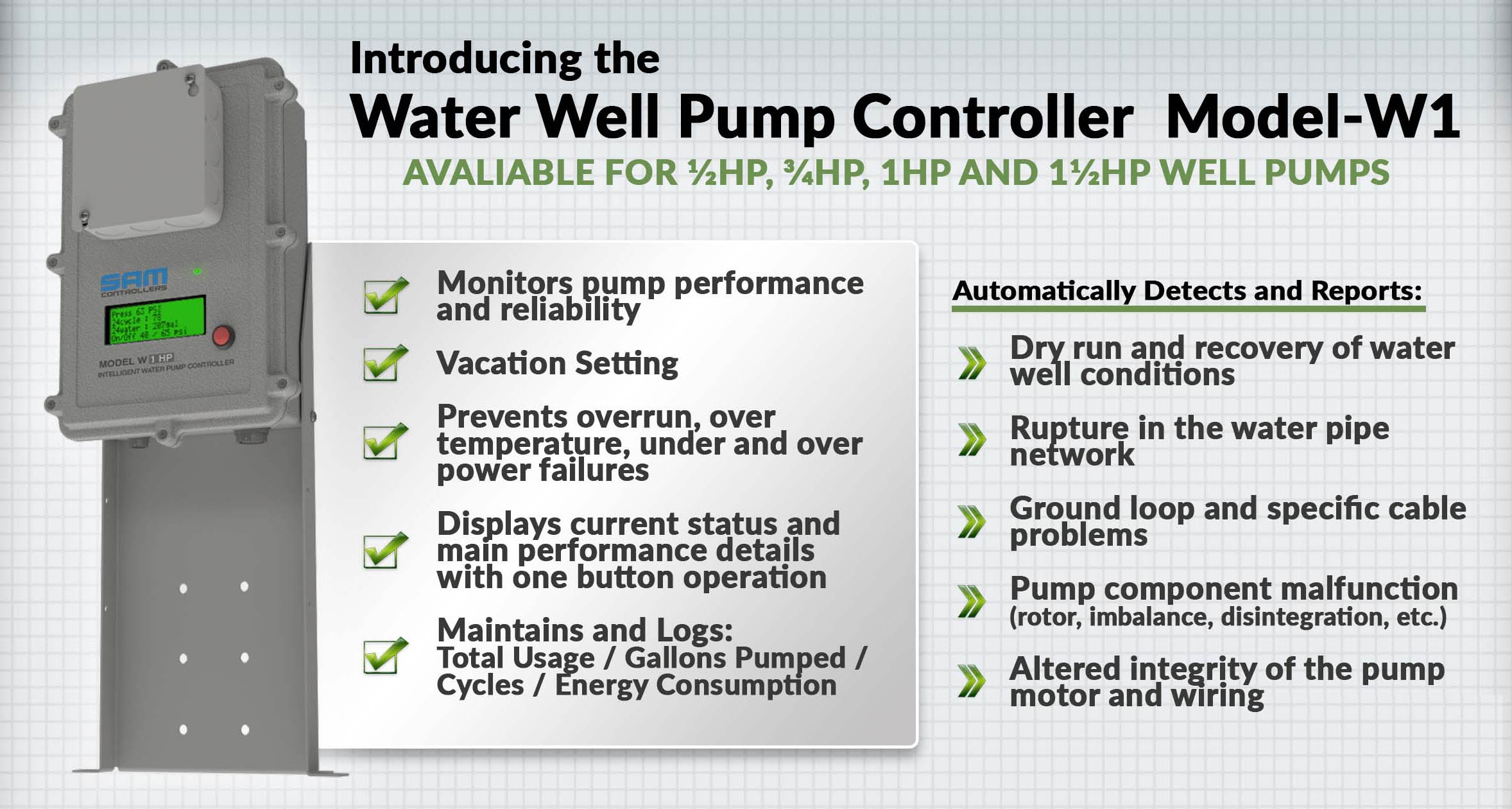
It’s like having an expert water well pump mechanic constantly observing the operation and letting you know what’s going on. The Water Well Pump Controller continuously monitors the water pump 24/7, constantly analyzing the performance and informing of the water pump status.


This advanced controller monitors the electric signature of the pump motor, which is the only way to acquire scientifically accurate performance data. Then, based on modeling and detailed calculations ensures consistent control and the best analytics possible.


The Water Well Pump Controller automatically tracks usage for daily/monthly comparisons, reporting any unusual patterns.

[info_list_father][info_list_son style=”icon” size=”20px” width=”40px” height=”40px” titlesize=”14px” titleclr=”#000000″ descsize=”12px” descclr=”#000000″ title=”Monitoring” icon=”fa fa-search” desc=”Pump performance and reliability and maintains total usage/pumped water/cycles/energy consumption”][info_list_son style=”icon” size=”20px” width=”40px” height=”40px” titlesize=”14px” titleclr=”#000000″ descsize=”12px” descclr=”#000000″ title=”Pump Safeguard” icon=”fa fa-thermometer-half” desc=”Prevents pump overrun and over temperature and under and over power”][info_list_son style=”icon” size=”20px” width=”40px” height=”40px” titlesize=”14px” titleclr=”#000000″ descsize=”12px” descclr=”#000000″ title=”Dry Well Recovery” icon=”fa fa-tint” desc=”Properly manages the pump during times of drought to prevent pump motor burnout,”][info_list_son style=”icon” size=”20px” width=”40px” height=”40px” titlesize=”14px” titleclr=”#000000″ descsize=”12px” descclr=”#000000″ title=”Simple to use” icon=”fa fa-user-circle-o” desc=”All operation and user configuration is done with one button”][info_list_son style=”icon” size=”20px” width=”40px” height=”40px” titlesize=”14px” titleclr=”#000000″ descsize=”12px” descclr=”#000000″ title=”Pipe Rupture Auto Pump Shutoff” icon=”fa fa-home” desc=”Upon detection of a pipe rupture the SAM well pump controller will shut off the pump and sound an alarm.”][/info_list_father]

Advantages of using the SAM Pump Controller 

Technical Details of the SAM Pump Controller  

The advanced controller capabilities are unprecedented in width and depth of data collected on water pump operation. We are offering SD card storage as an option along with BlueTooth, BLE, and WiFi capabilities as ordering options.


Also, we are continuing to develop iOS, Android and Windows applications for our customers.


We are inviting software developers to participate in our application development and offering an Open Source development platform for interested parties. Please contact us to discuss the details.


Water Well Pump installation and configuration guide:

  1. Plan a space for the installation
  2. Install the bracket firmly to the floor or the wall
  3. Install Controller on top of the bracket and secure the two side screws
  4. Disconnect power from your source, and make sure you are safe
  5. Remove the existing pressure switch wiring and body and replace with a properly installed Pressure Sensor using the appropriate fittings
  6. Connect the Pressure sensor cable connector to the receptacle on the Controller
  7. Connect the pump wires to wires marked “TO PUMP” – with the same colors
  8. Connect the ground wire (green wire) from power source and the pump ground wire, and connect with the Controller ground wire (Green wire)
  9. Connect the incoming power wire labeled “TO POWER,” to the Disconnect switch
  10. Connect any auxiliary equipment at this time
  11. Check all connections, according to the installation plan
  12. Connect power
  13. Follow the directions on the Controller screen

Enclosure Specifications:

Main block dimensions:  10 1/2″ Length x 7 3/8″ Width x 3 1/2″ Depth
Enclosure:  IP67 Aluminum NEMA Die Cast Box
Display dimensions:  6.30″ Length x 3.15″ Width x 2.17″ Depth
Enclosure: IP65 Polycarbonate, ABS NEMA 4
Floor Mounting bracket: StainlessSteel 15” Height x 6 ⅝ “ Width x 2” Depth
Wall Mounting bracket: StainlessSteel 5.5” Height x 9 ½ “ Width x ⅝” Depth
Design for indoor and outdoor (wet and semi-wet) locations.