
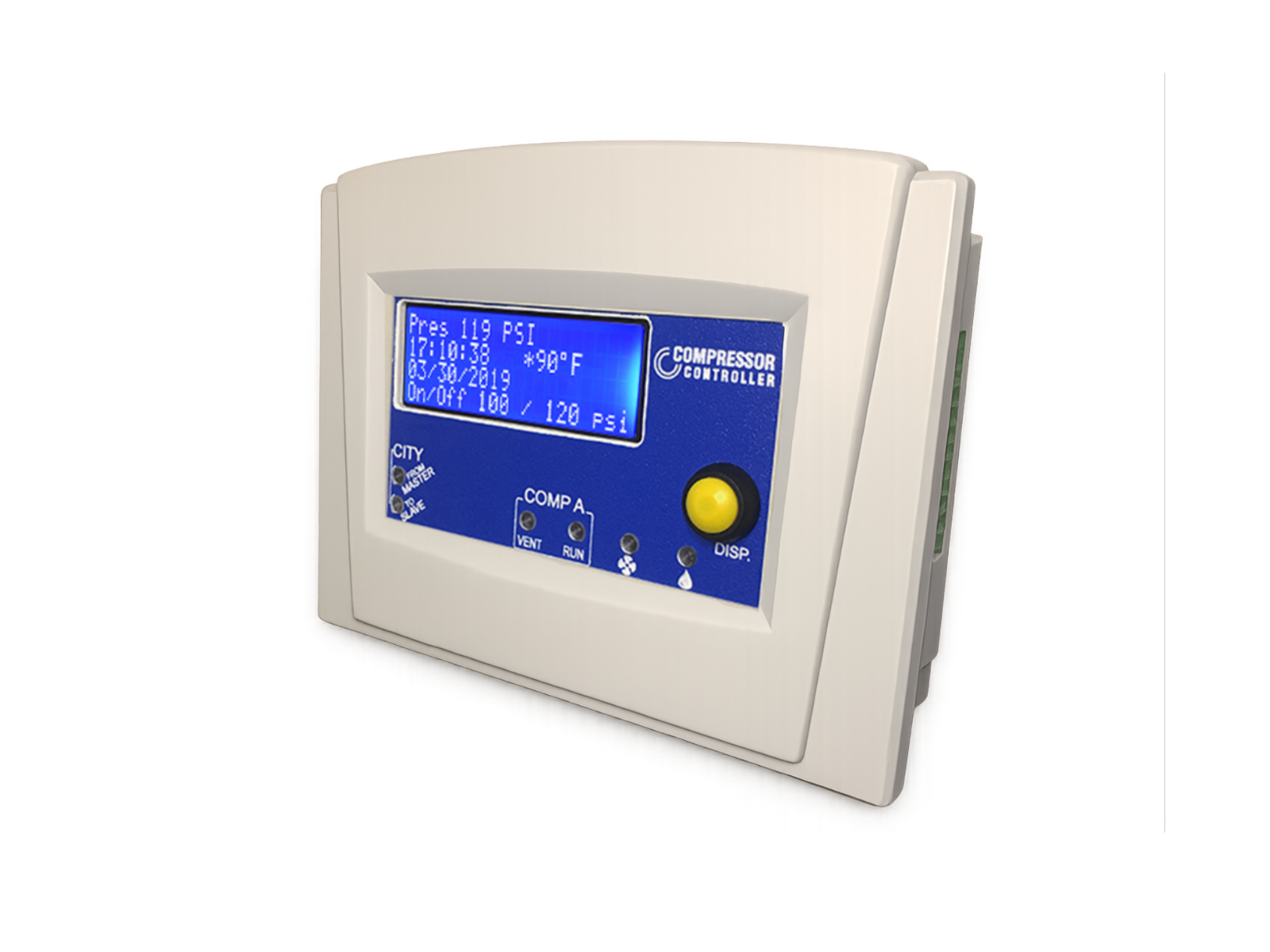
The Model R replaces drifting mechanical industrial air compressor controls with precision digital control. It reduces energy consumption, removes moisture from the air, and reports exactly what the compressor is doing — and when it needs maintenance.
Mechanical pressure switches drift up to 20% per year. Springs wear and temperatures swing. The compressor short-cycles or over-runs, and energy use climbs. Nobody notices until a switch sticks. Timer drains make it worse. They vent on a schedule. A timer drain bleeds tank pressure when the tank is dry. It leaves water behind when the tank is wet. That water travels downstream into tools, paint lines, and product.
The Compressor Controller Model R fixes all three at once. It replaces the switch with a drift-free digital sensor. It drains water only when runtime shows that water has accumulated. It manages start, stop, unloading, and venting from live measurements. Pecan Street ran a study funded by the Department of Energy. The study measured significant energy savings and a 100% reduction in compressed air moisture.
What it saves
Digital control cuts annual compressor energy costs by up to 40%. The controller typically pays for itself in under a year.
| Compressor HP | Average yearly savings | Average lifetime savings |
|---|---|---|
| 5 HP | $709 | $7,085 |
| 7.5 HP | $1,063 | $10,628 |
| 10 HP | $1,417 | $14,171 |
| 20 HP | $2,834 | $28,341 |
Estimates assume 8 hr/day operation at $0.1668/kWh, calculated with standard CAGI / U.S. DOE methodology over a 10-year life.
What it does
What it is
The Model R is a bolt-on digital control system for reciprocating piston compressors over 2 HP. It fits single-stage or multi-stage machines of any brand. The controller mounts in an enclosure. The pressure sensor threads onto the port that the mechanical switch vacated. Two wires land on the existing contactor. The controller adds control and changes nothing mechanical.
- R100 (CCR100) controls single-pump compressors.
- R200 (CCR200) controls duplex compressors. It alternates the pumps to even out wear. It runs both pumps together when demand requires double the flow.
Select model and configuration at the top of the page; the kit configurations are compared under Installation below.
How it integrates
The controller bolts onto reciprocating air compressors of any brand or age. It fits single-pump or duplex machines. It accepts single-phase 120/240 VAC or three-phase 208/480 VAC. The pressure sensor (A) replaces the mechanical pressure switch. It reads tank pressure to within 0.5 PSI across the operating range. The controller (E) drives the existing motor contactor (B). It acts only when readings cross the configured set points. The original starter, overload, and motor protection stay exactly where they are.
The smart drain (D) cycles on accumulated runtime, not a fixed timer. It opens just long enough to clear condensate. It closes before it bleeds tank pressure. The controller drives the intercooler fan (F) independently when head temperature crosses threshold. The CompressorCity link (G) is a single-wire bus. It lets multiple controllers share runtime, balance pump wear, and stand in for each other on failure.
Every variant uses the same operator interface, set-point structure, and diagnostic readout. Retraining is not part of the installation. Installation runs about a working hour for a journeyman electrician. The existing panel stays mounted. The supplied wiring harnesses bring labelled landings to every connection in the original control circuit.

Installation
Select the installation configuration level. Every configuration includes the controller and all sensors; the kits add hardware accessories.
| Configuration | Included Components | Assembly & Wiring |
|---|---|---|
| Controller Only | Controller and all sensors | Source enclosure, valves, and fittings; assemble and wire the panel. |
| Components Kit | Adds the IP67 enclosure, unloader and drain valves, and fittings | Mount components and complete panel wiring. |
| Pre-Wired Kit | Components Kit factory-wired with a labelled harness | Mount enclosure and connect relay outputs. |
| VFD Kit | Pre-Wired build plus integrated 10 HP variable-frequency drive | Mount enclosure, connect outputs, and commission drive. |
Installation Walkthrough
Installation must be performed by a qualified professional and may require field evaluation depending on local electrical codes and jurisdiction.
7-Step Quick Install Overview
- 1Power off the compressor at the disconnect. Verify that the contactor is de-energized.
- 2Mount the enclosure within reach of the contactor. Pre-Wired editions mount directly and connect to conduit.
- 3Wire the AC to DC supply from the supply side of the contactor to the 12 V DC input on the controller.
- 4Connect the relay outputs to the contactor coil terminals, replacing the mechanical pressure switch.
- 5Mount the sensors: Pressure goes into the receiver tap. Pump-head temperature goes on the cylinder head. Ambient goes near the intake.
- 6Set DIP switches for °C/°F, simplex/duplex, drain on/off, and fan on/off.
- 7Power on and verify the pressure set points, then run a test cycle. Field evaluation may be required. The Quick Start Guide details every step.
Each controller includes
- Digital pressure sensor (PRESS18200). Threads into a 1/8" NPTM port. Working range is 0 to 160 PSI, 250 PSI max.
- Pump temperature bolt-on sensor (DTB360). One with R100 kits, two with R200 kits.
- Ambient temperature and humidity sensor (DEDHT11). Digital and self-calibrating.
- Power and alarm hardware. Buzzer alarm, rocker switch, and a 110 to 220 VAC / 12 VDC power supply. A 200 to 277 VAC option is available.
| Specification | Detail |
|---|---|
| Compressor type | Reciprocating piston, single or duplex, >2 HP, single or multi-stage |
| Power input | 12 V DC (universal 95 to 277 VAC power supply included) |
| Processor | ATmega328p with real-time clock (±1 ppm) and onboard EEPROM data storage |
| Display | 20×4 LCD, LED backlit (green or blue) |
| Pressure sensor | Digital, factory laser-calibrated, 304 stainless steel, 0 to 160 PSI working / 250 PSI max |
| Temperature sensing | −40 to +125 °C range, self-calibrating |
| Ambient sensing | 20 to 90% RH, 0 to 50 °C |
| Relay outputs | NC-COM-NO, 10 A 250 VAC (use contactor or motor starter; relays do not drive the motor directly) |
| Enclosure rating | IP21. Indoor use, or sealed enclosure for outdoor. |
| Operating temperature | −10 to +40 °C |
| Dimensions | 7.1"W × 5.4"H × 2.3"D (panel cutout 6.6" × 4.7") |
| Assembled in | North Carolina, USA |
Important notes
- Keep all safety valves in place. The controller supplements safety components. It never replaces them.
- Drive the motor through a contactor, power relay, or VFD. The 10 A relay outputs do not carry motor current.
- Use factory components only. Third-party parts can cause unintended operation and void the warranty.
- You must register the warranty on all products.
FAQ
Will this work on a Quincy, Ingersoll-Rand, Champion, or FS-Curtis compressor?
Yes. It fits any reciprocating compressor of 2 HP or more that starts its motor through a contactor. Brand does not matter. It does not fit rotary-screw compressors.
What's the difference between R100 and R200?
R100 controls one pump. R200 controls two, and alternates lead and lag to even out wear. Choose R200 for duplex installations.
Does installation require an electrician?
Pre-Wired editions arrive factory-tested: mounting the panel and connecting the relay outputs completes the installation. The Components Kit adds panel wiring, comparable to wiring a contactor. Controller Only suits builders sourcing their own enclosure and valves.
Does it work on 230 V single phase?
Yes. The included supply accepts 110 to 220 VAC and powers the controller at 12 V DC. The relays switch the existing contactor and never carry motor current. Single-phase and three-phase systems both work.
Can the existing pressure switch stay as a backup?
Yes. Wire it in series on the NC contact as a fail-safe upper limit. Most installs retire it once the controller proves out.
Does the VFD edition qualify for utility rebates?
Many U.S. utilities pay industrial efficiency rebates that cover compressed-air controls, often per kWh saved. Confirm eligibility with the utility or program ally.
What happens after the warranty?
The warranty runs 90 days parts and labor from date of purchase. You must register the product. After that, parts ship from Pittsboro, NC at standard pricing and ticket-based support stays free. The controller has shipped since 2017.
Is international shipping available?
U.S. orders ship from Pittsboro, NC. For international orders, request a quote with destination and Incoterm.
Documentation & warranty
Every unit carries a 90-day parts-and-labor warranty from date of purchase. Ticket-based support comes direct from the people who build it in Pittsboro, NC.
How Model R connects
Hover, focus, or tap a marked connection to see its role in the installation.
