
Specifications
Physical-layer CAN fault isolation without a scope
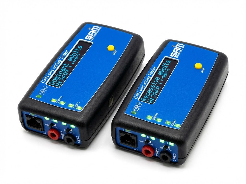
Find opens, shorts, connector resistance, termination errors, and unstable ground references before replacing a control module or opening the wrong section of harness. The CBWT02 actively exercises the two-wire CAN cable and measures the electrical response. It reports the result as plain-language fault codes, packet counts, and CAN_H/CAN_L voltage readings. Use one tester at a connection point or two testers to prove a complete cable run end to end. You do not need a laptop or message-layer decoding.
What it does that a scan tool cannot
- Tests the cable beneath the network - distinguishes physical-layer wiring problems from module and message-layer faults that can produce the same diagnostic trouble code.
- Works locally or end to end - use one unit to evaluate a connection point. Or place two units at opposite ends of the bus to verify packet delivery across the full run.
- Turns electrical behavior into six results - All Tests Pass, No Received Data, CAN_H short to ground, CAN_L short to ground, transmission error, and termination error.
- Shows the measurements behind the result - view transmitted, received, and errored packet counts plus dominant- and recessive-state millivolts on both data wires.
- Makes intermittent faults countable - monitor the Sent Data Fails counter while inspecting or manipulating a suspect connector or harness section.
- Provides audible end-to-end confirmation - paired testers chirp when test packets arrive. You can confirm successful communication without watching both displays.
- Operates as a self-contained field instrument - rechargeable battery, handheld enclosure, OLED display, status LEDs, and switchable 120 Ω termination.
Compare test configurations
| Configuration | What it verifies | Best used for |
|---|---|---|
| Single tester | Electrical condition at the connected point; Code 1 is expected when no second tester is present and no other fault is detected. | Connector checks, local shorts, voltage review, and initial fault isolation. |
| Two testers | Packet transmission and reception across the complete cable segment between both connection points. | End-to-end continuity, locating an open segment, confirming repairs, and separating cable faults from a suspect module. |
For a long or branched network, move the pair along the bus. Compare the code changes at each connection point. The Rev 3 manual includes a worked example that isolates a shorted module and a separate open cable on the same bus.
Diagnostic codes
| Code | Display | Interpretation |
|---|---|---|
| 0 | All Tests Pass | Test frames are transmitting and receiving successfully. |
| 1 | No Received Data | No partner-tester data received for 5 seconds. Expected during a single-tester check when no other error is present. |
| 2 | CAN H Short to G | CAN_H reads 0 V while the tester drives it to 3 V. |
| 3 | CAN L Short to G | CAN_L reads 0 V while the tester drives it to 1 V. |
| 4 | Transmit Error | The measured bus state does not match the transmitted state. Check for a wiring fault or traffic from another connected device. |
| 5 | Termination Err | CAN_H and CAN_L recessive-state voltages differ significantly. Check termination and electrical loading. |
Specifications
| Test method | Active transmit-and-listen; single-tester or paired end-to-end operation |
|---|---|
| Display | 16 × 2 OLED with DISP button |
| Displayed data | 6 diagnostic codes; transmit, receive, and error counts; dominant and recessive millivolts; sent-data failures |
| Indicators | 4 test-status LEDs; transmit and receive LEDs; charging-status LED |
| Audio | Receive chirp, user-toggleable |
| Connections | RJ-45: pin 4 = CAN_H, pin 5 = CAN_L; two banana-jack terminals |
| Termination | 120 Ω, switchable on/off |
| Power | Internal rechargeable battery or continuous Mini-USB power |
| Battery operation | Up to 3 hours |
| Charge time | Approximately 40 minutes from a Mini-USB charger |
| Enclosure | Handheld plastic enclosure; IP24; optional protective boot |
| Dimensions | 98 × 64 × 36 mm (3.86 × 2.52 × 1.03 in) |
| Weight | 260 g (0.62 lb) |
| Application | Physical-layer testing of two-wire CAN cabling and equivalent two-wire data lines; no message decoding |
FAQ
Does the CBWT02 replace a CAN scan tool?
No. A scan tool reads messages, module states, and diagnostic trouble codes. The CBWT02 tests the physical cable and electrical response. The two instruments answer different questions and are complementary.
Do I need two testers?
Not for a local check. One tester can identify shorts, termination imbalance, transmission errors, and wire voltages at its connection point. You need two testers to verify packet delivery across an entire cable segment.
Can it help find an intermittent harness fault?
Yes. Watch the packet and Sent Data Fails counters while inspecting a suspect harness or connector. A changing failure count provides repeatable evidence that the electrical path is unstable.
Does it decode J1939, CANopen, or diagnostic messages?
No. It is intentionally message-agnostic and evaluates the physical two-wire CAN path. Use the appropriate scan tool or CAN analyzer when you must decode message content.
What does the termination switch do?
It connects or removes the internal 120 Ω termination inside the tester. The correct position depends on the network under test. If Code 4 appears on a long network, change the termination setting. This can help distinguish a termination problem from another wiring fault.
Can I connect it to an energized machine or vehicle?
No. The tester actively transmits CAN frames. Power down the system under test and isolate batteries where applicable. Prevent every connected actuator or module from operating before you attach either tester.
How long does the battery operate?
Up to 3 hours per charge. The tester can operate continuously from Mini-USB power.
Quick-start procedure
- Power down the tester and every device or module connected to the CAN bus under test. Isolate batteries where applicable.
- Confirm that no motor, actuator, brake, engine, control output, or other connected equipment can operate during testing.
- Connect CAN_H and CAN_L using the banana terminals or RJ-45 pins 4 and 5.
- Set the 120 Ω termination switch for the network configuration, then power on the tester.
- Wait for the error screen. With one tester, expect Code 1 alone. With two testers, Code 0 confirms successful transmission and reception.
- Press DISP to review packet counts, wire voltages, sent-data failures, and the receive-beep setting.
- After a repair, repeat the test from the same connection points and record the code, counter, and millivolt results.
Read the complete safety and operating instructions in the User Manual before placing the tester into service.
Safety, use, and origin
- Country of origin: Pittsboro, North Carolina, USA.
- Intended users: trained technicians, electrical engineers, and qualified maintenance personnel working on low-voltage data networks.
- Environmental rating: IP24. The tester is not for submersion, prolonged weather exposure, explosive atmospheres, or operation outside normal indoor ambient conditions.
- Excluded work: high-voltage propulsion circuits and energized safety-critical systems, including SRS, pyrotechnic, braking, stability-control, and fuel-system circuits.
- Service: no user-serviceable internal parts. Opening or modifying the tester can void applicable warranty terms.
Documentation and support
The CBWT02 User Manual, Revision 3 (July 2026), covers single- and two-tester operation, every display and LED state, connector pinout, and specifications. It also includes a worked two-fault diagnostic example, a component-level fault-reference table, and complete safety information. Use the User Manual link for the current Revision 3 PDF.
Warranty terms, current lead time, purchase-order support, and application review are available directly from SAM Controllers in Pittsboro, North Carolina.

