
Nobody notices compressed air until it stops. Then everyone asks why.
Compressor rooms often run two or more compressors in parallel, each with its own pressure switch. Each switch reacts to the same pressure drop alone.
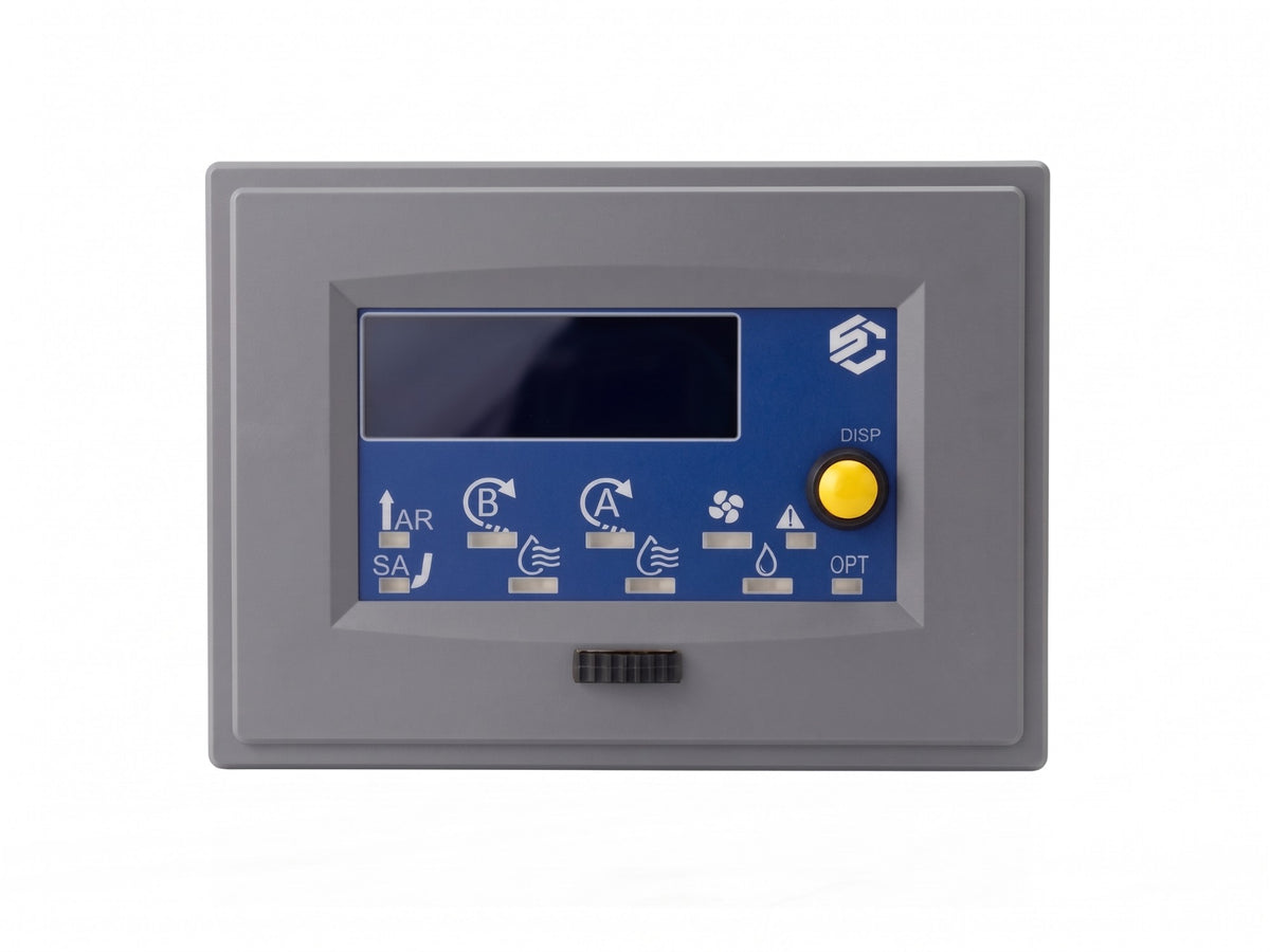
The Compressor Controller Model C runs those compressors as one cluster. It starts the unit with the lowest runtime first and starts a spare when pressure keeps falling. It names each fault it detects and raises a maintenance-due alert from counted runtime. One CompoNET cluster links up to 16 C1 or C2 controllers, so one unit can stop for service while the others keep the air on.
- One unit takes most of the run hours and wears out first.Starts the unit with the lowest runtime first.
- At peak demand, pressure sags while a spare unit stands idle.Starts the spare when pressure keeps falling.
- A failed unit goes unnoticed until the pressure falls.Detects the fault and names it.
- Service on one unit stops the air.The other compressors keep the air on.
- Maintenance follows the calendar instead of run hours.Raises a maintenance-due alert from counted runtime.
What the Model C does
-
Virtually eliminate downtime
Service a compressor while the air stays on.
A service day or a failed unit no longer means an air outage you have to explain.
When one compressor stops for service or fails, the others continue to supply the required airflow. The lead role moves between controllers, so a unit leaves or rejoins the cluster without a stop.
-
More life out of your air compressors
One compressor no longer wears out first.
Wear spreads across every compressor, so service intervals stay predictable.
The Model C starts the unit with the lowest runtime first, so run hours spread across the cluster. On a C2, it alternates compressors A and B when their temperature or runtime difference passes a set limit.
-
Repairs start with a cause
Know about a fault before anyone asks.
When something fails, the Model C names the fault, so the repair starts with a cause, not a search.
It detects and flags
- Pipe and tank ruptures
- High and low temperature
- Run times past the set limit
- A broken wire or missing pressure sensor
- Over-pressure
- Inconsistent readings
- After a restart, a power loss mid-cycle
-
Planned service, fewer surprises
Service what needs it, when it needs it.
You plan service from the runtime each controller counts since the last service, not from the calendar.
Each controller raises a maintenance-due alert, and the Cluster Display holds the maintenance schedule for the whole cluster. It logs run hours, on/off cycles, over-run and over-temperature events, temperature extremes, and drain and vent cycles per compressor.
-
Less routine upkeep
Drained, vented and cooled without a reminder.
The Model C drains, vents and cools every compressor on its own. It does these jobs better than a timer or a mechanical switch.
A timer drains on a fixed schedule, whether the tank holds water or not. A switch reacts only after the pressure passes its limit. The Model C opens the tank drain and the vent valve as part of each compressor cycle. It runs the cooling fan from measured temperature, not on a timer or by hand.
-
Air status in your building system
Alarms reach the people who can act.
With the signalling package, your building system knows the air status, so nobody walks to the compressor room to check.
Four dry-contact outputs report the status, and four inputs accept HALT and other remote signals. A light tower shows the same status at the machines.
Dry-contact outputs and light tower - Alarm
- Warning
- Operational
- Maintenance
-
Steady pressure at peak demand
More air when demand peaks.
The spare units you already paid for add capacity at peak demand instead of standing idle.
If pressure keeps falling, the Model C starts another compressor on the network. If pressure still falls, it starts the next one.
Pressure Time Compressor A Compressor B Compressor C- Demand rises
- Model C starts compressor B
- Pressure still falls, it starts compressor C
- Pressure recovers
-
Compatible with VFD compressors
Drives and manages your VFD compressors.
The Model C is compatible with variable-frequency drives. It actively runs each drive and manages the compressor speed.
The VFD control option runs a variable-frequency drive on each motor with active speed control. Each motor needs its own drive. Check the utility rebates in your area.
What it is
The Model C is a compressor controller for industrial and commercial compressed-air systems, where a reliable air supply matters most.
Easy to set up. No programming.
If you can use a remote control, you can configure the Model C. It starts from factory settings. You adjust them through the menu with the included remote.
- Readings you can trust. Digital sensors stay precise and do not drift, so the Model C acts on true values for the best performance. A 2-wire sensor reads pressure. 1-Wire sensors read pump and motor temperature.
- One controller runs the whole compressor. Dedicated 5 A dry contacts switch the contactor, vent, drain and fan. The panel needs no separate drain timer or fan switch.
- Status at a glance. The 20×4 OLED shows status and live readings. An ambient light sensor keeps it readable in a bright or a dim room.
- Room to add compressors. Every unit links to other controllers over the CompoNET CAN bus, so a cluster grows one unit at a time.
- Events with a time stamp. A real-time clock dates the logs, and a buzzer alerts people at the machine.
- A contact for the event you choose. One more 5 A dry contact reports the event you select: compressor running, over temperature or maintenance due.
-
C1
Controls one compressor.
-
C2
Controls a duplex compressor with two compressor heads that feed one tank. A menu setting allows both heads to run at the same time during high demand.
Order the Model C as
- A controllerThe Model C on its own, for installers who build and wire their own panel.
- A Pre-Wire kitThe controller with its wiring prepared, so the installer mounts it and connects the compressor.
- A complete systemThe controller and the parts around it, ready for the compressor room. SAM Controllers confirms the contents when it sizes your cluster.
How the cluster links
Every Model C includes CompoNET, a CAN bus that links up to 16 controllers into one cluster. Add the parts the site needs on the same bus.
- Cluster Display Set up and control the cluster from a web interface. It holds the maintenance schedule.
- CompoNET gateway Remote monitoring and logging over WiFi, for one controller or the whole cluster.
- Building system Receives status outputs and sends HALT and remote inputs.
- LeadC1
- C2
- C1
- +Up to 16 per cluster
What the bus carries
- Runtime. The controller with the lowest runtime starts first.
- Start commands. Another compressor starts when pressure keeps falling.
- The lead role. It moves to another controller when a unit leaves or rejoins the cluster.
Running Model R controllers too? Every Model C also includes the Compressor-City link, up to 8 units per network. A site with the Cluster Display can run any number of clusters.
Specifications
Installation and setup
-
Power and wiring
The controller runs on 12 V DC. It connects through three edge connectors and back-panel connections.
-
Sensors
Digital 1-Wire sensors measure pump and motor temperature, plus room temperature and humidity. A digital 2-wire sensor reads system pressure.
-
Settings
Settings arrive factory programmed. You adjust most parameters with the remote at the unit. Select °C or °F in the menu.
What we need to size your cluster
SAM Controllers sizes each cluster to the site. Have these answers ready.
Join the waitlist SAM Controllers contacts waitlist members first when units are available.
- Total air demand in CFM, with the maximum and minimum demand
- Output of one compressor at peak performance, in CFM
- Peak-performance temperature of each compressor
- Minimum and maximum pump operating temperature
- Maximum motor operating temperature
- Minimum acceptable system pressure and maximum system pressure
- Confirmation that your electrical supply can run every compressor at the same time
FAQ
How does the Model C differ from the Model R?
The Model R controls one or two compressors. The Model C runs a room of compressors as a cluster. It includes the CompoNET bus as standard, and you can add building status signals and active VFD control.
How many compressors can one cluster run?
Up to 16 C1 or C2 controllers per CompoNET cluster. With the Cluster Display, a site can run any number of clusters.
Does it work with VFD compressors?
Yes. The Model C controls their speed. Each motor needs its own drive.
What happens when one compressor fails?
The other compressors hold the required airflow. The controller shows the fault on its front panel. The signalling package also switches the Alarm output to your building system.
Does it replace the safety valves?
No. Keep your safety valves. The controller supplements safety components and never replaces them.
How do I get one?
Join the waitlist with the form on this page. Send your site details with the sizing form above.